- Drive
-
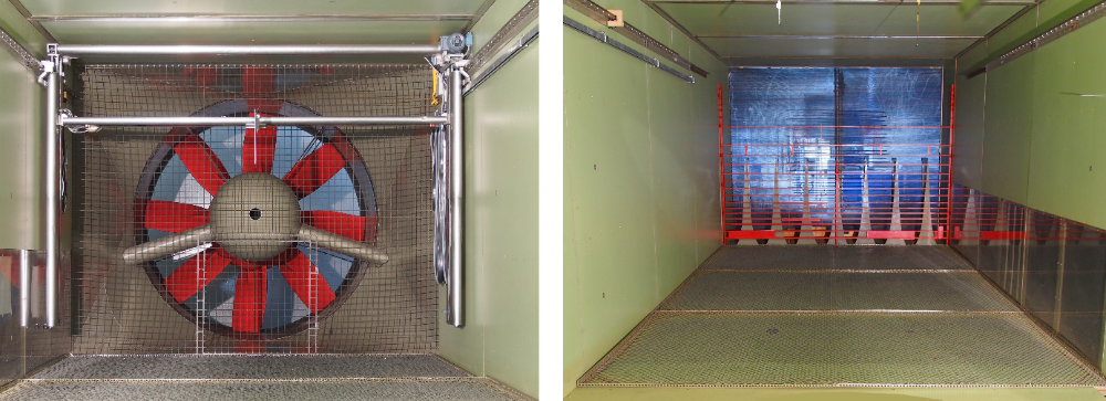
electrohydraulic; blower fan speed continuously adjustable
- Drive power
-
maximum 120 KW
- Maximum velocity
-
19 m/s
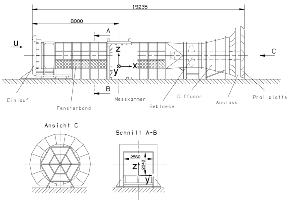
- Cross section of the test section
-
2,5 m x 2,0 m [w x h]
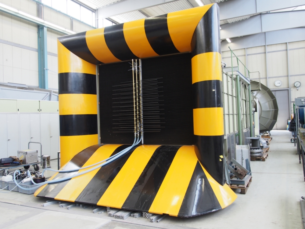
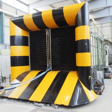
In the Boundary-Layer Wind Tunnel (Eiffel type with rectangular channel cross-section and closed measuring chamber; GWK) of the IAG, certain velocity profiles and turbulence structures can be generated by various combinations of inlet obstacles and ground roughness in order to simulate the turbulent boundary layer flow of the natural wind.
The GWK can therefore be used to investigate the flow around buildings (e.g. to determine wind loads) and to measure velocity fields over complex topography (e.g. flow around hills or steep slopes).
Contact
Bernd Peters
Dr.-Ing.Academic Staff Member working group Environmental Aerodynamics