Core competencies
The noise simulation of helicopters with regard to high-speed and blade-vortex-interaction noise is based on the acoustic analogy of Ffowcs Williams and Hawkings, for which a high-resolution CFD calculation is evaluated.
For validation purposes, IAG owns an instrumented model helicopter with a take-off mass of almost 5 kg. In addition to much more expensive wind tunnel measurements, valuable measurement data for different conditions in free flight can be obtained with this model helicopter.
Power requirements and aeroacoustics are becoming equally important for future rotor developments. The optimal design of ground plan and profiling is therefore essential.
A central component of the simulation is the consideration of the elastic deformation of the rotor blades (fluid-structure coupling). For this we use beam models with different levels of detail (Euler-Bernoulli, Timoshenko beams, ...).
For comparability with wind tunnel measurements or flight tests, trimming to the specified forces and moments is of crucial importance.
Dynamics
The dynamic behavior of the helicopter, in particular the rotor blades, is calculated using CSD (Computational Structure Dynamics) methods. The codes "HOST" of Airbus Helicopters and the commercial code "CAMRADII" are used. The dynamic information is needed for the aerodynamic simulation of a helicopter, since the position and deformation of the blade has a direct effect on the flow around it.
More on dynamics: Trim
The simulation of helicopters generally poses a threefold problem, since it does not only consist of the calculation of the flow itself, but also of the elastic reaction of the rotor blades and the simultaneous maintenance of the desired trim condition.
The trim state of a rotor is a selection of characteristic rotor parameters, such as the total thrust generated and the roll and pitch moments introduced into the fuselage via the rotor mast. Other common parameters are the amplitudes of the blade movements. The purpose of trimming is to bring these parameters to given values. In principle, the number of parameters which can be trimmed is limited by the number of control options on the rotor. If, for example, three control inputs of a swash plate (i.e. the collective and the two cyclically changed blade angles) are available, these can be used to bring the three parameters thrust, roll and pitch torque of the rotor to the desired values. In the case of a so-called active rotor, where e.g. small flaps at the rotor blades can be controlled, further parameters could be considered in the trimming.
Aerodynamics
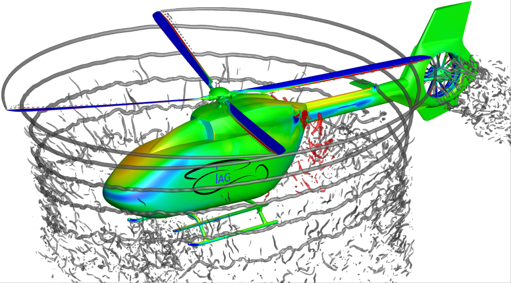
The main task of the helicopter and aeroacoustics working group is the simulation of aerodynamics. The CFD (Computational Fluid Dynamics) code "FLOWer" of the DLR, which was significantly extended and expanded at the IAG, is primarily used for this purpose. In the past, the DLR code "TAU" was also used for such investigations. In addition, a DG method is being developed for the future: Discontinous Galerkin (DG)
Aeroacoustics
Aeroacoustics is calculated based on the flow solution. For this purpose, the code "ACCO" was developed and is used at the IAG.
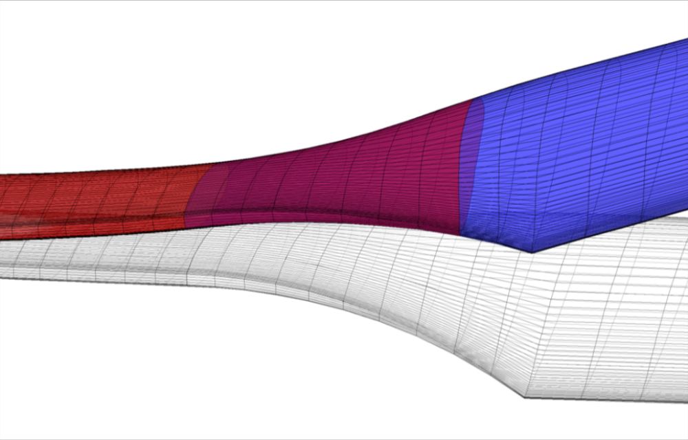
In high-speed flight, circumferential and forward speeds overlap strongly at the leading blade and result in local supersonic flow, which is terminated by a shock wave. As this superimposition effect changes continuously during the rotation, these shock waves are created from about 50° azimuth and reduced again beyond 140° - combined with strong pressure fluctuations at the blade surface. The temporal correlation of these shock wave phenomena over the blade length means that this form of pressure fluctuation is essentially radiated forward as sound. This effect is particularly strong at highly loaded rotors with relatively few blades, symptomatical for example for the Bell UH-1 with two-blade rotor.
In general, edge vortices develop at the tip of the blade, similar to the rigid wing aircraft, due to the generation of lift. Due to the induced velocity through the rotor disc, these are normally transported downwards. In forward flight they are transported spirally backwards.
If the sink rate is comparable to the induced speed, the blade tip vortex and the rotor blades lie in the same plane, so that the following blades can hit the vortices of the preceding ones. At certain azimuth angles (in the range of 45° and 315°) the vortices are then "cut open" across the blade, which leads to strong pressure fluctuations at the blade due to the vertical velocity induced by the vortex (upwind/downwind) shortly before or after the vortex core. This is associated with a corresponding increase and decrease in the effective angle of attack and thus in the lift, which is closely linked to the pressure distribution on the blade.
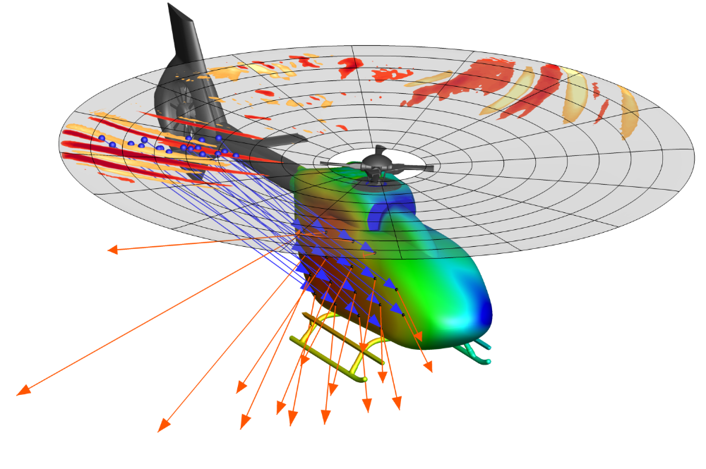
A more detailed analysis of the temporal sequence over the length of the blade shows that these vortex-induced pressure fluctuations are mainly radiated obliquely towards the front and bottom, i.e. in the direction of the landing point.
apl. Prof. Dr. Manuel Keßler

Manuel Keßler
apl. Prof. Dr.Deputy Head of Institute / Head of working group Helicopters and Aeroacoustics