Methods for polar measurements
The rectangular test section is 3.15 m in length and the cross-section is 0.73m x 2.73m. The airfoil models have a span of 0.73 m and are mounted vertically between two rotary tables in the tunnel walls. Typical chord lengths of the airfoils are 0.5m, 0.7m and 1m. The test section is surrounded by a low-pressure chamber which prevents that air is passing into the test section through leaks. The blades of the wind tunnel fan, which have a cross-section of 2.7m, can be adjusted at rest, and therefore allow an optimal adaptation of the drive to each desired flow velocity. The rotational speed of the fan is computer controlled, therefore the flow velocity can be adjusted in dependence of the environmental parameters like temperature, total air pressure and humidity: This allows to carry out long measurements with constant dynamic pressure or Re-number, even if the blockage of the test section changes. The data acquisition and the control of the experiment is done by a PC, the values are provided with standard wind tunnel corrections and plotted online.
Tunnel-wall corrections at the Laminar Wind Tunnel
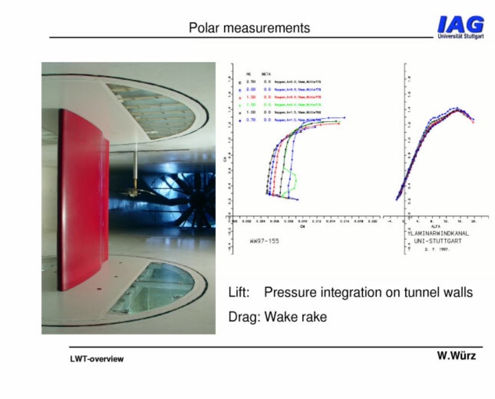
Measurement of lift and drag in the Laminar Wind Tunnel
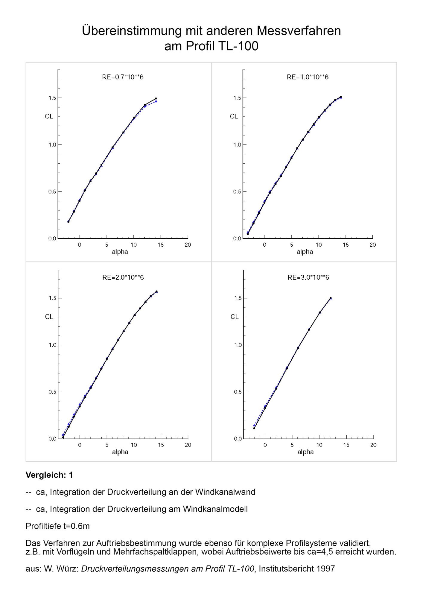
The lift is determined by the integration of the pressure distributions on the wind tunnel walls. The difference of the pressures determined on both walls is proportional to the lift of the wind tunnel model. This indirect measuring method has some impact on the model construction, which can be simplified compared to models built for measurements with a balance. In addition, the models can be sealed with respect to the rotary tables. The lift values obtained by this indirect method agree very well with other measuring procedures.

The drag is determined by the integration of the total pressure loss in the wake profile. The wake rake is mounted downstream of the model in a distance of about 30% of the chord length. A computer controlled traversing system allows an automatic adjustment in the center of the wake. During the measurement, the rake is moved with constant velocity in spanwise direction and the mean airfoil drag is determined.
The pitching moment of the airfoil is determined by a load cell from the torque around the c/4-point of the model.
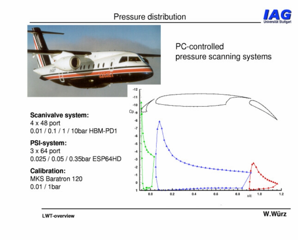
Four Scanivalve systems with 48 ports each can be used in combination with HBM pressure transducers to determine the pressure distribution on the model. Recently a PSI pressure scanning system was installed with a total of four ESP-64HD electronic pressure scanners covering the typical range of differential pressures measured at the Laminar Wind Tunnel.
Additional measurement techniques
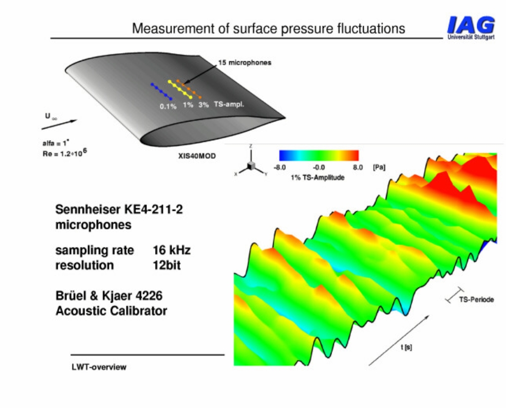
To determine unsteady pressure fluctuations or acoustic measurements, special microphones and calibration facilities can be used.
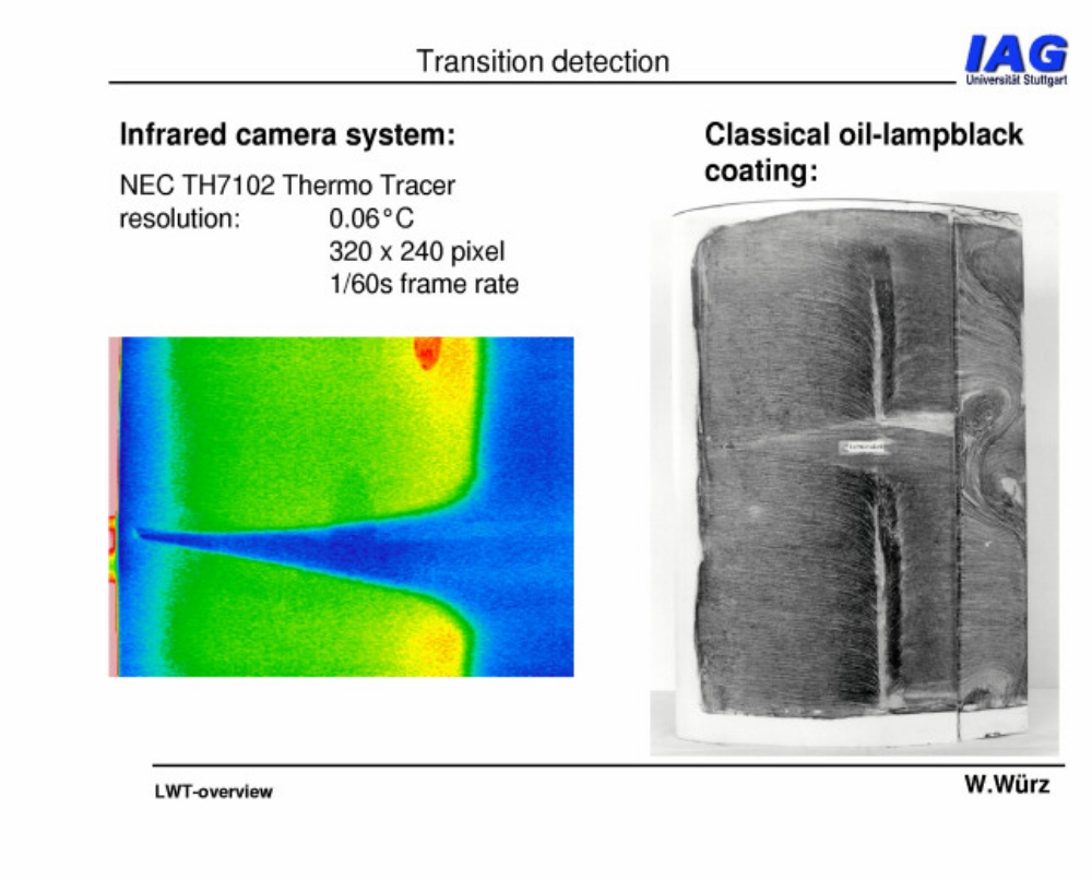
The visualization of flows can be done by
- coating methods
- tufts
- smoke probes
- infrared camera FLIR X6541sc
An infrared camera with a resolution of 0.025K monitors the transition position during the measurements.
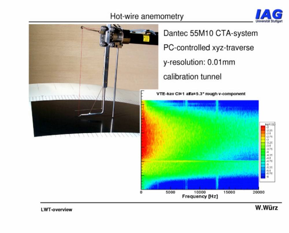
A special boundary-layer probe controlled by a computer has been developed for hot-wire measurements. This allows for highly effective measurements of airfoil boundary layers.

For special investigations a high-resolution stereo-PIV system can be used. With the help of pulsed Nd:YAG lasers all three velocity components in the light sheet can be determined simultaneously as an instantaneous picture of the flow.

For the measurement of trailing-edge noise of two-dimensional airfoil models the hot-wire based CPV method can be used. It was developped and validated at the Laminar Wind Tunnel.
Contact

Ulrich Deck, M.Sc.
Head of working group Laminar Wind Tunnel