INAFLOWT
INnovative Actuation Concepts for Engine/Pylon/Wing Separation FLOw Control, Design, Build and Wind Tunnel Test
Current Projects

FOR 2895
Unsteady flow and interaction phenomena at High Speed Stall conditions
A research initiative funded by DFG (FOR 2895), HGF and DLR.

Contact: M.Sc. Johanna Kärner, Dr.-Ing. Thorsten Lutz
DOXWING – Aerodynamic analysis of boxwing configuration in combination with distributed electric propulsion.
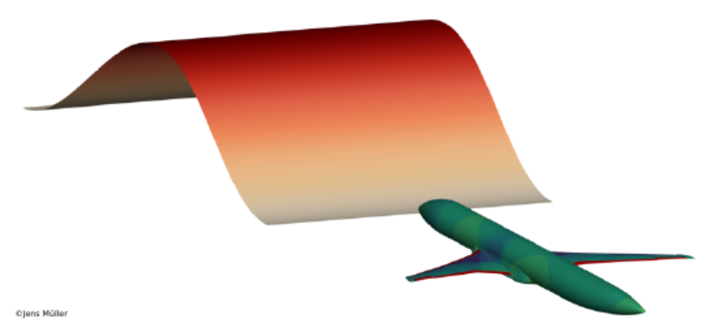
In the LuFo VI-3 joint project DOXWING, a boxwing configuration is combined with distributed electric propulsion (DEP) to reduce emissions towards sustainable aviation by increasing the aircraft efficiency. In addition, the required power is generated by a hydrogen fuel cell. Project DOXWING takes advantage of synergy effects of the combination of boxwing and DEP in order to design a more efficient and more silent aircraft with short take-off and landing (STOL) performance.
Together with the project partners Bauhaus Luftfahrt, TU Berlin – led by IFB of the University of Stuttgart – the aerodynamics, propulsion, wing structure and aeroacoustics are studied. Furthermore, wind tunnel experiments using wing and propeller models are conducted to validate the results. Finally, based on the previous results, a final aircraft concept is created and evaluated.
Background and problem: Distributed electric propulsion (DEP) has proven its potential to increase the maximum lift coefficient. This is an important factor to achieve the desired STOL characteristics in DOXWING. A boxwing reduces the induced drag at cruise flight when comparing to a conventional configuration at identical wing span. In addition, aerodynamic interactions between the two horizontal wings and the distributed propellers are expected, which may further increase the maximum lift coefficient and the propeller efficiency. The systematic investigation of those complex aerodynamic phenomena with CFD parameter studies is the focus of the analysis done by IAG.
Objectives of the Aircraft Aerodynamics Group: The aerodynamic interactions of a boxwing configuration with DEP are investigated using CFD, namely (U)/RANS methods with Actuator Disc/Actuator Line models or fully resolved propellers. At first, the decisive parameters are identified, which are then studied in detail to obtain synergy effects. The simulations are validated by wind tunnel experiments of the TU Berlin. In the end of DOXWING, the aerodynamics of the final aircraft concept is analyzed with CFD.
| Supported by: | |
 |
 |

Move-IntegR – Aerodynamic Design of Shock Control Bumps on a HLFC Wing
Contact person: M.Sc. Jens Müller, Dr.-Ing. Andreas Waldmann, Dr.-Ing. Thorsten Lutz
Integrated multifunctional control surfaces are being researched in the LuFo V-3 joint project Move-IntegR, with particular focus on the requirements of high aspect ratio, slender, and laminarized wings.
The project is divided into two topics – the development of structural concepts for long, slender flaps and the development of shock control bumps (SCBs) with variable positions on the spoilers of a hybrid laminar flow control (HLFC) wing. The first topic in particular focuses on a low-cost integration solution for multifunctional control surfaces on an efficient, high aspect ratio wing, which enables a high manufacturing rate. The second topic of the project, involving work at IAG, deals with wave drag reduction and buffet control by means of shock control bumps on a HLFC wing. These measures enable an extension of the operational range of HLFC wings as well as a reduction in emissions through reduced fuel consumption. In addition to aerodynamic design and assessment of the aerodynamic effectiveness, the structural feasibility and the system integration of SCBs as a morphing spoiler are considered. The work conducted on SCBs in the Move-IntegR project is based on the findings of the LuFo V-1 project LDAinOP.
Together with the Institute of Aerodynamics and Flow Technology of the German Aerospace Center (DLR), the IAG conducts aerodynamic design of shock control bumps. While the DLR Institute of Aerodynamics and Flow Technology focusses on a reduction of wave drag, the IAG aims at influencing the transonic buffet boundary in order to extend the operational flight envelope. The positioning of the shock control bumps on the spoilers is of particular importance in the context of a HLFC aircraft wing, with the need to account for realistic integration of the SCBs on the wing. Due to the constrained positioning of the SCBs relative to the shock system that develops on the wing, the influence of variable camber (VC) to increase the effectiveness of SCBs is investigated in addition to fixed-position SCBs. Apart from the aerodynamic effectiveness of the SCBs, the structural feasibility of SCBs as a morphing spoiler and the system integration are taken into account by the DLR Institute of Lightweight Systems and the DRL Institute of Flight Systems.
Objectives in the IAG work packages:
- Optimization of shock control bumps with varying position and crest height on relevant 2D sections of the HLFC wing in terms of buffet onset delay. Extension of the SCB restricted to the position of the spoiler with and without regard to structural feasibility of the bump shape.
- Increase of the effectiveness of SCBs for buffet onset delay by application of variable camber (VC) employing trailing edge flaps.
- Transfer of the 2D SCB design results to the 3D HLFC wing. Evaluation of the SCB effectiveness to influence the buffet boundary of the entire aircraft.
- Analysis of the effect of additional wing deformation and a variation of the laminar to turbulent transition location on the SCB effectiveness.
- Extension of the existing design guidelines for SCB design.
| Support: |
GNOSIS - Holistic evaluation of electric flight
Contact: M.Sc. Michael Schollenberger, Dr.-Ing. Thorsten Lutz
GNOSIS: The overall objective of the LuFo joint project GNOSIS, led by RWTH Aachen, is the holistic analysis of the potential of electric flight of different configurations. The IAG contributes to the holistic view with an aerodynamic evaluation of the configurations.
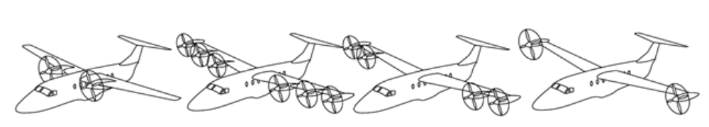
Background and problem: The use of electric propulsion has a fundamental impact on the aerodynamic design of aircraft. Due to the variable position of lighter and more compact electric propulsion systems and the separation of power supply and propulsion generation, new unconventional propulsion integrations become possible. The resulting interactions between the propulsion systems and the other aircraft components can be used to increase aerodynamic performance and thus reduce power requirements. Different concepts with such interacting propulsion systems are currently being investigated (e.g. distributed propulsion systems, high-lift propellers, wing tip propellers, fuselage-integrated propulsion systems), but a general comparison of the concepts under the same boundary conditions with regard to their energy efficiency has not yet been carried out. The basis for the aerodynamic evaluation of the different configurations is a CFD analysis based on steady-state and, if necessary, transient Reynolds-averaged Navier-Stokes equations (U/RANS). The configurations are to be compared with each other and with the reference configuration in terms of aerodynamic quality of the wings, propulsion efficiency and flap efficiency. The investigation is not so much aimed at deepening the understanding of the detailed effects that occur, but rather at evaluating and comparing the effectiveness of the concepts. The results obtained are further used for aerodynamic modelling as well as for the extension of existing preliminary design procedures in order to increase the prediction and optimization capabilities for future efficient designs.
Objectives in Aircraft Aerodynamics Group work packages: The primary objective in the aerodynamics work area is to perform a general comparison of different electrical configurations. Three principally different configuration concepts will be numerically analyzed and compared with each other and with a conventional reference configuration. The aerodynamic potentials and limitations of the different concepts will be determined depending on relevant design parameters. Currently used pre-design methods are not able to capture the aerodynamic interactions with sufficient accuracy. The second goal is therefore to compare these with the complex CFD results and, if necessary, to derive simplified aerodynamic methods for improving the faster preliminary design procedures.
| Supported by: |
 |
DISPROP – Aerodynamic and aeroacoustic modeling of closely operating propellers for DIStributed PROPulsion
Contact: M.Sc. Mario Firnhaber Beckers, M.Sc. Michael Schollenberger, Dr.-Ing. Thorsten Lutz
DISPROP: The main objective of the Clean Sky 2 project DISPROP is to improve the current aerodynamic and aeroacoustic analysis and design capabilities for distributed propulsion aircraft. To achieve this goal, the overall concept of DISPROP is a multidisciplinary collaboration of various proven specialists in the fields of aircraft design, aerodynamics and aeroacoustics, and wind tunnel research and modelling. Essentially, a number of promising hybrid-electric distributed propulsion configurations are being investigated both experimentally in wind tunnel tests as well as numerically using state-of-the-art CFD/CAA methods . This combined numerical and experimental analysis will provide a detailed understanding of the flow physics of propellers operating in close proximity to the wing. This is a necessary step to evaluate different concepts and to validate the numerical methods.
Background and problem: Distributed propulsion is an emerging technology that promises to increase the overall efficiency of an aircraft and thereby reduce CO2 and other greenhouse gas emissions. Unlike conventional commercial configurations, which are typically powered by two or four engines mounted locally on the wing, distributed propulsion consists of a larger number of smaller propulsion systems distributed across the span of the wing. The main advantages of distributed propulsion systems are higher overall efficiency due to favourable interaction between the wing and the propeller slipstreams For this purpose, modern aerodynamic and aeroacoustic simulation methods need to be validated, in particular for the interaction in distributed propulsion systems, in order to ensure satisfying analysis and design of distributed propulsion systems for hybrid-electric aircraft.
Objectives in aircraft aerodynamics group work packages: The main goals of the work done at the IAG are on one hand the validation of the European standard aeronautical CFD code TAUfor its ability to reproduce and capture the relevant propeller-wing interactions using different propeller simulation methods (ACD, ACL, fully resolved simulation), and on the other hand the evaluation of different distributed propeller concepts, in particular with respect to their ability to increase high-lift potential in the start and climb scenarios.
| Supported by: |
 |
VELAN – Distributed electrical propulsion
(translated from original title: Verteilte elektrische Antriebe)
Contact: Maximilian Kern M.Sc. Michael Schollenberger, Dr.-Ing. Thorsten Lutz
VELAN: Directed by IAG, the aviation research program LuFo financed project comprises the analysis, verification and transfer of aerodynamic, aeroacoustic and flight dynamics effects on distributed electric propulsion. The project work is carried out in a multidisciplinary network at the University of Stuttgart consisting of the IAG, the Institute of Flight Mechanics and Flight Control (iFR) and the Institute of Aircraft Design (IFB).
Background and problem: Electrical propulsion allows the distribution of propellers along the wing. Thereby, the kinetic energy in the propeller slipstream is used to increase wing lift and the impact of the flow around the wing on the propeller inflow is utilized to increase efficiency and thus enabling a weight and drag reduction through a lower wing depth. The synergistic use of distributed propellers for flight control opens up the possibility for reducing or even removing the vertical stabilizer. The increased velocity in the propeller slipstream promises improved high-lift performance through a higher flap efficiency and noise-reducing elimination of slats. Therefore, the configuration investigated in this project consists of propellers distributed over the wingspan, wing tip propellers, the possibility of differential thrust and the resulting reduction or removal of the vertical stabilizer. The aerodynamic effects are investigated numerically with regard to an integrative design of wing and propeller, including the influence on the high-lift behaviour. Influences on noise mechanisms and noise reduction measures will also be investigated. In order to experimentally validate the principal results of the project and to verify them under realistic conditions, measurement flight campaigns including noise measurements are planned with the unmanned technology platform e-Genius Mod, already available at the university.
Objectives in aircraft aerodynamics group work packages: In the field of aerodynamics, three work objectives shall be achieved: first, a deepening of the understanding of the aerodynamic interactions of distributed propulsion systems with each other and with the wing in terms of flow physics, second, an assessment of distributed propulsion as high-lift devices, third, the development of a methodology workflow to integrative design propellers in consideration of the interactions. With the combined design of propellers and wing potentials of the interactions shall be intensified.
| Supported by: |
(INTELWI-USTUTT) / Aerodynamischer Entwurf und Bewertung dynamischer Steuerflächen für die Reduktion von Böenlasten und Entwicklung einer smarten digitalen Infrastruktur
Contact Person: M.Sc. Jens Müller, M.Sc. Marco Hillebrand, Dr.-Ing. Thorsten Lutz
| Logo |
 |
A major goal of the aircraft design process derives the Flightpath 2050, which aims to reduce CO2 emissions by 75% per passenger kilometer by 2050. Part of this will be achieved through mass savings, which will result in progressively more elastic aircraft structures. These structures must be approved in the aircraft design in accordance with the CS - 25 design specification. An important part of the certification process is the consideration of gust loads, which are largely responsible for the dimensioning of the structure and thus the mass. In order to reduce the resulting gust loads on the wing, which has a positive effect on the structural mass and thus on the aircraft mass, two load alleviation options are available in the form of passive and active gust load alleviation.
In this context, the INTELWI project as a part of the Luftfahrtforschungsprogramm (LuFo) Vl-1, investigates active gust load alleviation concepts for an "intelligent" wing of future aircraft generations. The concept is based on an autonomous reaction of the wing on external disturbances caused by maneuvers and gusts via load reduction. In the ideal case, unsteady load fluctuations in gusty and turbulent inflow conditions can be fully compensated for in the so-called "1g" wing, and the wing can be produced and tested as a self-sufficient component. This reduces the wing load significantly and thus the required structural weight, while passenger comfort is significantly increased. In addition, such a load-minimized wing promises significant savings in resources and CO2 emissions.
Within the INTELWI project, the focus of the IAG is on the active gust load alleviation. The load alleviation concepts investigated in INTEILWI are based on the project Potenziale für drastische Lastminderung bei Verkehrsflugzeugen (PoLamin), where flap deflections of leading and trailing edge flaps in cruise flight have been investigated for gust load alleviation on a rigid wing-fuselage configuration. The application of the leading and trailing edge flaps at the same time is a unique characteristic of PoLamin and INTELWI. Here, the leading edge flaps are applied for torsional and the trailing edge flaps for lift control.
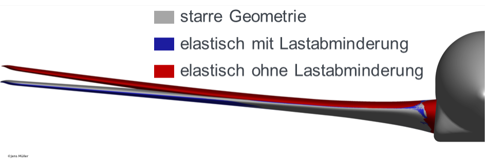
In INTELWI, aeroelastic effects are added at the IAG by using CFD-CSM simulations, taking the avoidance effect during an idealized 1-cos gust interaction of the structure into account. The avoidance effect has a reduction on the applied loads and an impact on the effectiveness of the load control systems due to torsional as well as bending tilting. First, the aeroelastic effects on the active gust load alleviation system are investigated using a conventional aircraft configuration. This is followed by applying the concept on a high aspect ratio, high elasticity wing. Here, significant wing deformations are to be expected due to the new design. These deformations will be reduced using the gust load alleviation system. These researches enable an outlook if high aspect ratio, high elastic wings can be realized in the future. The research is done in close cooperation with the Technical University of Braunschweig (TU-Braunschweig) and the Technical University of Hamburg (TUHH). The TU-Braunschweig is investigating the reduction of maneuvering loads using dynamic actuated control surfaces. The TUHH is working on the design of actuators and system technical boundary conditions. Another project partner from the University of Stuttgart is the Institute of Aircraft Systems (ILS), which is designing and demonstrating a smart digital infrastructure (SDI) in the area of systems engineering.
Research aims of the IAG within the INTELWI project:
- Evaluation of the influence of an elastic wing on the effectiveness of gust load alleviation using spanwise segmented leading and trailing edge flaps.
- Application and evaluation of the aeroelastic load alleviation concept to a high aspect ratio and highly elastic wing.
- Evaluation of the overall concept of dynamic control surfaces for an intelligent load control on a conventional and high aspect ratio wing with regard to load alleviation
| Flügeldeformation aufgrund der Interaktion mit einer vertikalen 1-cos Böe mit und ohne Lastabminderungssystem im Vergleich zur stationären flight shape in CFD-CSM gekoppelter Simulation. © Jens Müller |
 |
INTELWI Partner: DLR-Institut für Aerodynamik und Strömungstechnik (Leitung DLR-Teilprojekt), DLR-Institut für Aeroelastik, DLR-Institut für Faserverbundleichtbau und Adaptronik, DLR-Institut für Flugsystemtechnik, DLR-Institut für Instandhaltung und Modifikation, DLR-Institut für Systemarchitekturen in der Luftfahrt, DLR-Insitut für Systemdynamik und Regelungstechnik, Airbus (Gesamtverbundleiter INTELWI), Airbus Defense and Space, Liebherr Aerospace, Diehl Aerospace, FFT GmbH, Pace AG, Technische Universität Berlin, Technische Universität Braunschweig, Techniche Universität Hamburg, Technische Universität München
Funder: Bundesministerium für Wirtschaft und Klimaschutz (BMWK), Luftfahrtforschungsprogramm (LuFo), Förderkennzeichen 20A1903L
ELFLEAN - Electric wing tip mounted propellers
Contact Person: M.Sc. Michael Schollenberger, Dr.-Ing. Thorsten Lutz
Projekt Description
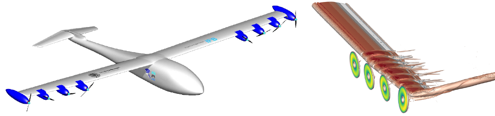
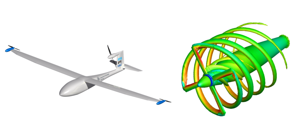
The aim of the project ELFLEAN as part of the Federal Aviation Research Programme of Germany (LuFo) V-3 is to investigate aircraft configurations with wingtip mounted propellers. An advantageous use of the aerodynamic interactions between the propellers and the wing vortex system, should lead to an increase in the energy efficiency of the configuration and therefore to a reduction of the power requirement. The reduction of the power requirement is intended to compensate for the central disadvantage of electric aircraft, the power supply. In addition a reduction in pollution and noise emissions should be enabled. By reducing the power requirements and the resulting savings in direct operating cost (DOC), the concept has the potential of a commercial advantage over conventional configurations. In the longer term, the concept should contribute to emission-neutral aviation.
ELFLEAN
is a multidisciplinary project of three institutes of the University of Stuttgart, the Institute of Aircraft Design (IFB), the Institute of Flight Mechanics and Flight Control (iFR) and the Institute of Aerodynamics and Gas Dynamics (IAG). The interdisciplinary character is intended to optimize the efficiency of the entire system before maximizing a partial aspect and thereby increase the chances of success of the concept. At the IFB flight tests should be carried out with a scaled unmanned demonstrator platform with wingtip mounted propellers based on the electric aircraft e-Genius. The aim is to quantify the impact of wingtip propellers on flight performance and assign them to the various effects. The flight mechanical characteristics of the configuration are investigated at the iFR. At the IAG, in order to expand the theoretical understanding of the aerodynamic interactions, detailed investigations are carried out by (U)/RANS-based numerical models.
Background
Wingtip mounted propellers use the aerodynamic interaction that occurs between the propeller and the wing vortex system. On the one hand, the tangential velocity of the propeller slipstream can be used to counteract the induced downwash of the wing tip vortex and thus to reduce the induced drag of the wing. On the other hand, the wing tip vortices can increase the inflow velocity of the propeller blades and thus the propeller thrust. Both effects result in a reduced power requirement of the overall configuration.
The interactions are dependent on flow conditions as well as geometric and operational parameters, in particular the relative propeller position upstream (tractor configuration) and downstream (pusher configuration) to the wing. Due to the large number of occurring effects and design parameters, wingtip mounted propellers are a complex technology.
Work at the IAG
IIn the field of aerodynamics, the questions should be clarified, which aspects contain the aerodynamic interactions in detail, how these can be numerically determined, verified by flight tests and taken into account for the design of wingtip mounted propeller configuration. Various numerical methods are used for the propeller simulation, approximating models such as Actuator Disk and Actual Line as well as a fully blade resolved calculation by Chimera rotation.
The project steps are:
- Verificate the numerical methods for the simulation of aerodynamic interactions between wingtip mounted propellers and the wing vortex system.
- Understand the aerodynamic interactions in more detail.
- Generate a detailed database of the design parameters.
- Investigate the aerodynamic design of wingtip mounted propellers.

Completed projects:

Virtual Aircraft Model for Studies on the Interaction with Atmospheric Turbulence (VitAM-Turbulence)
Contact person: M.Sc. Jens Müller, Dr.-Ing. Thorsten Lutz
Background and motivation
An essential component of future aircraft development is the ability to describe an aircraft and its characteristics as accurately and comprehensively as possible in the computer with the associated simulation models in the sense of a product as a virtual aircraft model. In the context of the joint project VitAM, the idea of the Virtual Aircraft Model is to be implemented and demonstrated in industrially relevant applications.
The IAG is investigating the effects of realistic atmospheric turbulence on the loads and aerodynamics of transport aircraft. In addition to fundamental investigations on the propagation of turbulence in CFD simulations, two approaches to modeling atmospheric disturbances in CFD simulation are compared. These are the Resolved Atmosphere Approach (RAA), which records all interactions between aircraft and atmospheric turbulence, and the Disturbance Velocity Approach (DVA), which records only the influence of the disturbances on the aircraft, but not the effect of aerodynamics on atmospheric turbulence. While the RAA requires a very high computational effort, the DVA offers the advantage of using a coarser network resolution and thus a lower computation time.
Objectives in the IAG work packages
- Creation of an interface for turbulence injection in CFD simulations.
- Performing tests to propagate turbulence through a simple flow field.
- Determination of the necessary network resolution and numerical parameters.
- Investigation of the interactions between inflow turbulence and flow around a profile / airfoil using DVA and RAA. Characterization of the correlation between the turbulence fed in and the load fluctuations at the profile/wing.
- Comparison of the simulation approaches RAA and DVA.
- Simulation of the flight of a complete aircraft configuration (ATRA) by realistic atmospheric turbulence using DVA and RAA.
INAFLOWT
INnovative Actuation Concepts for Engine/Pylon/Wing Separation FLOw Control, Design, Build and Wind Tunnel Test
Contact person: M.Sc. Junaid Ullah, Dr.-Ing. Thorsten Lutz
Background and scope
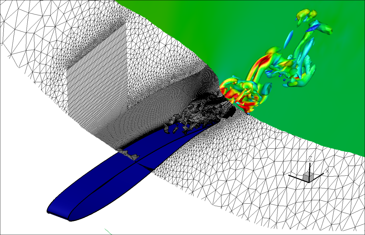
The strong increase in air traffic together with the ambitious goal of the EU to reduce COx and NOx levels by up to 90% by 2050 compared to 2000 poses major challenges for aircraft manufacturers. Optimizing the engines of passenger aircraft is one way of getting a little closer to the prescribed goal. Special attention is paid to dual-flow engines with a very large bypass ratio, so-called UHBR (Ultra High Bypass Ratio) engines. In terms of fuel consumption, these engines have significantly better characteristics than those in which a large part of the flow is directed through the core engine. The large nacelle diameter of the UHBR engines and the maintenance of a certain ground clearance to the runway result in a close coupling between engine and wing when integrated into the wing. In order to avoid a collision of the high-lift systems with the engine during landing, no leading edge slats are used in the area of the UHBR engine. The turbulent flow from the engine components and the pylon, as well as the missing acceleration effect of the leading edge flap, lead to flow separation in the wake of the UHBR engine. The consequences are a stall occurring approx. 2° earlier and a degradation of the maximum lift by approx. 10%. By active flow control, especially by suction and blowing on the flow surface, the separation areas can be reduced and the stall can be shifted to higher angles of attack again. However, most flow actuators that have been part of numerical and experimental investigations have the disadvantage that they cannot be used for applications in civil aviation due to their low robustness, high weight and high mass flow requirement. Therefore, within the Clean Sky 2 project INAFLOWT, the EU has set itself the goal to develop flow actuators which can be used on the wing of a passenger aircraft.
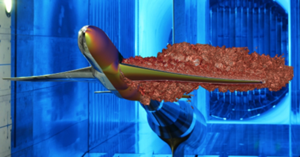
Wind tunnel tests with a configuration representative for a high-lift system-engine combination of an airliner under realistic inflow conditions should show whether the developed actuators bring the hoped-for advantage. Within the AFloNext (Active Flow- Loads & Noise control on Next Generation Wing) project, actuators operating according to the synthetic jet and pulsed jet principles have already been tested on the wind tunnel model mentioned above. Especially the results with the pulsed jet actuator were very promising. However, the pulsed jet actuators have the disadvantage of an excessively large mass flow requirement, which cannot be met by bleed air from the engine alone. The SaOB (Suction and Oscillatory Blowing) actuator developed by Tel-Aviv University can close this gap by additionally blowing out the extracted air. At the same time, the boundary layer suction has a positive effect on the tendency of the flow to become detached. Therefore, the SaOB actuator, whose advantages over the other state of the art actuators have so far been demonstrated almost exclusively under laboratory conditions, will be investigated in detail under realistic conditions within the framework of the INAFLOWT project. A benchmark study at the end of the project will compare the actuator technologies to highlight the improvements achieved with the SaOB actuator.
Project partners and work at the IAG
Five research institutions and universities from four different countries are actively involved in the INAFLOWT project. The Tel-Aviv University (TAU), Israel Aerospace Industries (IAI), the Aerospace Research and Test Institute in the Czech Republic (VZLU), the Central Aerohydrodynamic Institute in Russia and the IAG. While TAU and TsAGI deal with the experimental work, the other project partners are active in the numerical field. TAU mainly deals with the experimental investigation of the internal actuator flow and the wind tunnel tests of a generic, downscaled wind tunnel model. The generic wind tunnel model is used to test different actuator concepts in order to select the most promising concept and transfer it to the more cost-intensive wind tunnel tests of the large model. TsAGI has the experimental means with the large subsonic wind tunnel T-101 to test the configuration under flight-relevant inflow conditions. IAI's main task is to design the generic wind tunnel model to ensure that, despite the differences in the wind tunnel configurations and Reynolds numbers, the same flow conditions prevail as on the large model. VZLU performs actuator internal simulations to optimize the actuator geometry with respect to pressure losses and to provide actuator boundary conditions for the external flow simulations on the high-lift configuration.
At the IAG, the flow around both high-lift configurations is numerically investigated. Simulations are performed both with and without actuators. The investigation of different actuator concepts on the generic configuration by means of CFD should limit the number of actuator configurations to be investigated in the wind tunnel in addition to the definition of the actuator positions. The simulations of the large model with the final actuator configuration will finally be used for a benchmark study in which comparisons to the actuators used in the AFloNext project will be made.
For the CFD simulations at IAG the flow solver DRL TAU-Code is used. For the URANS calculations of the external flow around the high-lift configurations, the actuators are modelled only through the suction holes and blow-off nozzles. A complete modelling of the actuators would be associated with an unrealistic computing time, despite the use of the computing clusters of the HLRS. The transient boundary conditions at the outlet of the suction hole and at the inlet of the blow-out hole are taken from the internal actuator simulations of VZLU.
The validation of the simulation results by means of experimental data also provides the possibility to evaluate the limits of the URANS application using the flow solver DLR TAU code for simulations with flow actuators and thus to draw conclusions for future numerical investigations of actuator influences on the external bypass flow.
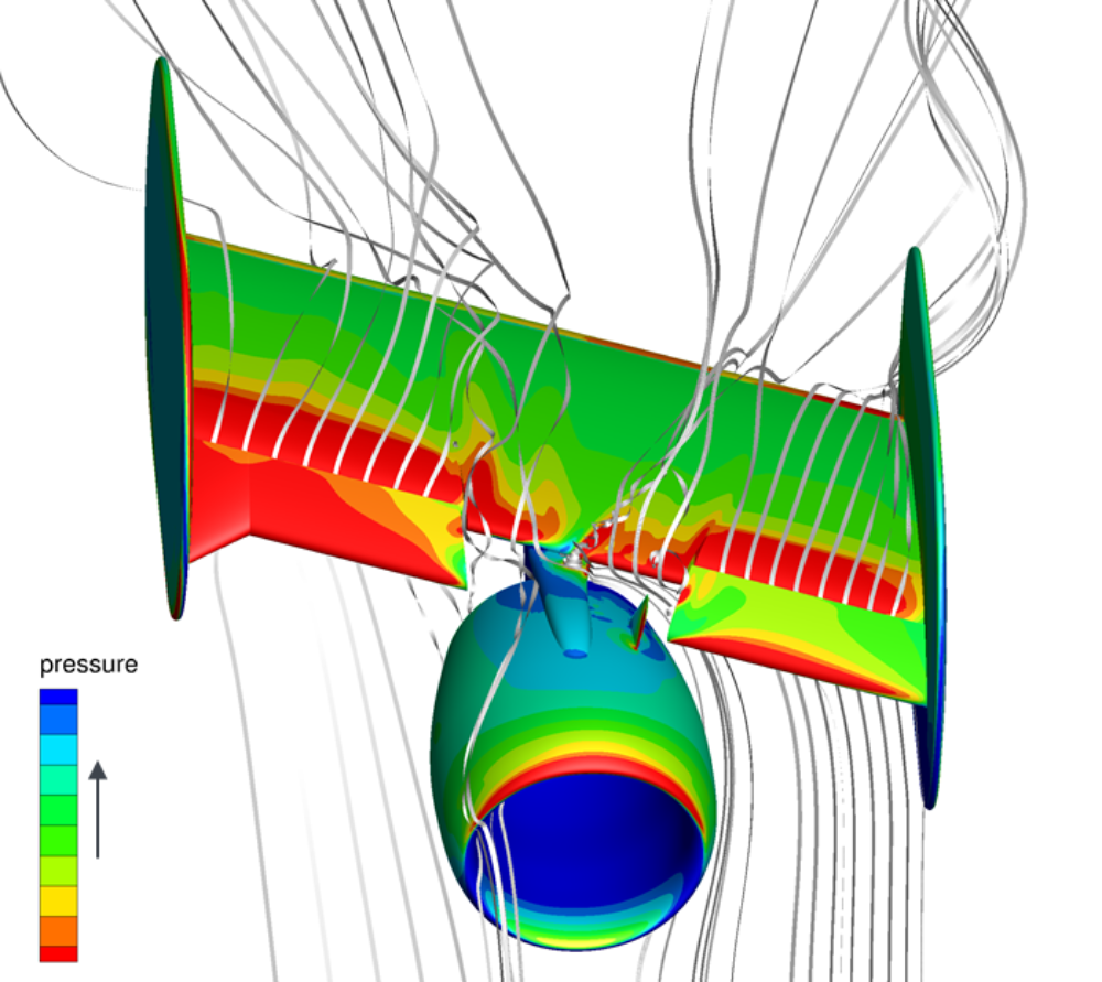
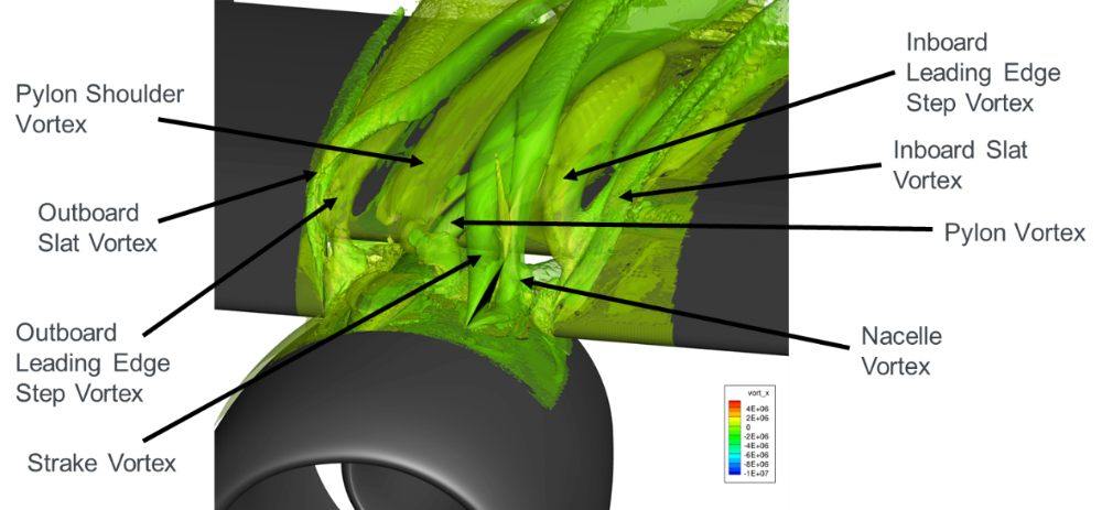
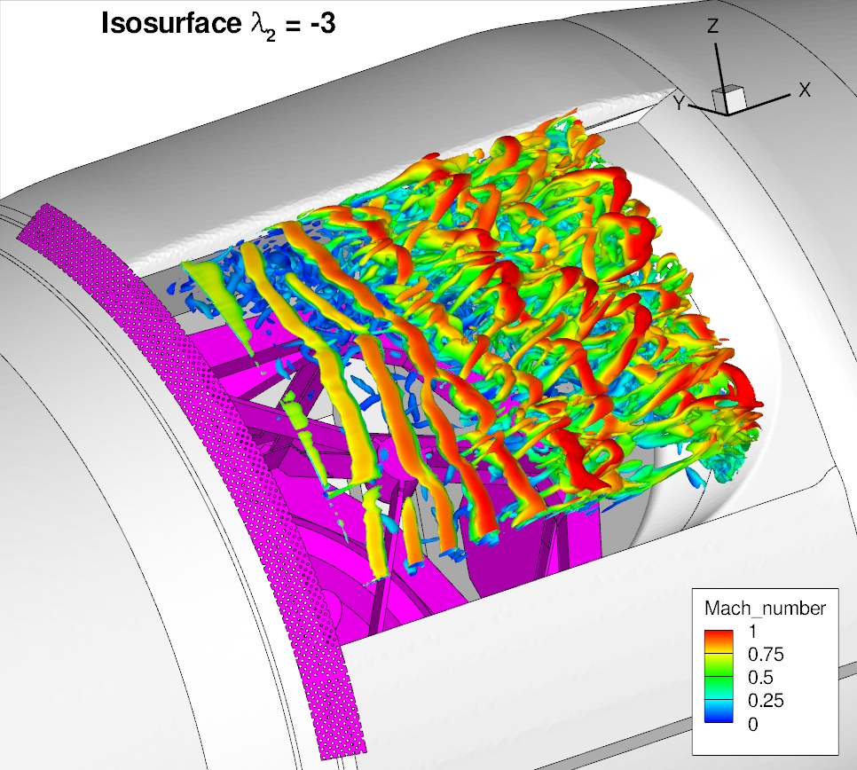
Results
Characterization of the vortex structures in the slat cut-out area of the large model behind the UHBR engine at an angle of attack of 27°.
Background and motivation
In order to characterize the behavior of passenger aircraft beyond the boundaries of the flight envelope, an understanding of the flow physics involved is crucial. Predictions of the stall behavior of the wing, including the formation of vortices and turbulent structures, their propagation in the wake, and their interaction with the tailplane are essential for the structural integrity and control of the aircraft. Therefore, in the two project phases of the DFG project LU 809/8, the flow-physical mechanisms of the development of separated wake flows of commercial aircraft and their interaction with the tailplane were to be investigated and analyzed in detail. Since such conditions, which are far from the design point, are difficult to predict by wind tunnel experiments or flight tests, reliable and accurate simulation methods are key for these studies.
As part of the project, simulations were carried out using the flow solver DLR TAU Code on the NASA Common Research Model (CRM), a generic transport aircraft. These were validated with wind tunnel data from the European Transonic Wind Tunnel (ETW) and subsequently analyzed. The inflow conditions included the low-speed stall regime from incipient flow separation to fully separated flow in the post-stall, as well as cruise speeds at which shock-induced flow separation and transonic buffet occur. It became apparent that hybrid RANS/LES methods are key for the prediction of the position and turbulence in the wake and specific models are necessary for the different flow conditions.
The work packages also included investigations on different configurations of the CRM. The influence of the tailplane and its angle of attack as well as the influence of the wind tunnel mounting on the wake and tailplane loads were investigated.
The analyses carried out allow an improved understanding of the flow phenomena occurring on the wing, in the wake as well as on the tailplane of an airlianer outside the boundaries of the flight envelope.
Work at the IAG
- Creation of specific computational meshes for the different inflow conditions and configurations
- Selection and further development of suitable numerical models for the simulation of flow separation and wake for the different inflow conditions.
- Validation of the simulation results using experimental data
- Flow physical analyses of the flow separation, the turbulent wake as well as the wake-tailplane interaction for all inflow conditions and configurations
Contact: Dipl.-Ing. Rouven Mayer, Dr.-Ing. Thorsten Lutz
Background and motivation
A wing in laminar flow leads to a significant reduction of the aerodynamic resistance compared to a wing in turbulent flow. Airbus has been working with partners on this technology for many years. However, the realisation of a laminar wing for operational use still requires a great deal of effort, such as answering questions on the economic production and durability of the very smooth surfaces required.
The Low Drag Aircraft (LDA) technology program, which has been running since 2008, is designed to demonstrate the technical maturity of an NLF (Natural Laminar Flow) wing up to technology maturity level 6. Within the framework of the LDAinOP subproject, key technologies for this type of transonic wing are to be investigated. In addition to improved laminar retention in climb flight through the intelligent use of a flap, this flap is also to be used in cruise flight to adjust the wing curvature and thus to position the shock wave occurring in the transonic speed range. This is of interest in so far as the natural laminar flow requires less wing sweep. As a consequence, the flight Mach number above which wave resistance occurs is considerably reduced. On the basis of shock positioning, various measures for wave resistance reduction will therefore be investigated. In the past, the so called Shock Control Bump (SCB) has proved to be an efficient control measure. However, this only works when the position is correct with regard to the compression impact and tends to have a detrimental effect when the flight Mach number is lower, so that adaptive structural concepts are to be investigated within the framework of the project.
Works at the IAG
Within the framework of the LDAinOP project at the IAG, an SCB design for wave resistance reduction at high transonic flight Mach numbers for a modern laminar wing using numerical methods is being developed. A CFD-based numerical process chain is used, which allows the numerical optimization of SCBs. Based on the optimization results, industrially applicable design guidelines are developed. In addition, the IAG, with its many years of experience, supports the project partners in the structural implementation of the SCB design. Consequently, one goal of the project is to demonstrate the structural feasibility of such adaptive structures.
Contact: Dipl.-Ing. Rouven Mayer, Dipl.-Ing. Steffen Bogdanski, Dr.-Ing. Thorsten Lutz
Background and motivation
With regard to the development of future transport aircraft, resistance reduction and the associated lower fuel consumption play a central role. Laminar wings show great potential here. The aim of the BUTERFLI project, carried out in European-Russian cooperation, is an in-depth analysis of the underlying aerodynamics in order to establish laminar wing technology in industry in the medium term and thus improve the flight performance of future commercial aircraft. For this purpose, the BUTERFLI project investigates different phenomena with experimental and numerical methods, which are related to a laminar wing operating in the transonic speed range. In addition to the buffet, i.e. the repeated detachment and reapplication of the boundary layer combined with an impact and lift oscillation, on a laminar profile and a turbulently flowed around supercritical profile, cross-flow instabilities on a swept wing are also investigated. In addition, investigations are carried out using various flow influencing techniques. In addition to contour bumps (Shock Control Bumps (SCB)), active measures such as plasma actuators are also used.
Works at the IAG
Within the framework of the BUTERFLI project, 3D-SCBs are being investigated and designed at the IAG, which will both reduce the characteristic impedance occurring in the transonic velocity range and increase the flight range limit specified by the occurrence of Buffet. For a laminar profile, numerical optimizations of the SCBs are carried out at the IAG. An existing, CFD-based, numerical process chain is used, which includes RANS simulations in addition to automated, high-quality networking of the profile geometry with a structured network. URANS simulations will then be performed for selected SCBs to provide in-depth insights into buffet behaviour, buffet boundaries and buffet amplitudes.

Background and motivation
With high flight Mach numbers and lift coefficients, highly complex, transient impact-interface interactions occur at the wing, which can be associated with local or complete impact-induced detachments. The detached transient flow may strike the tail and cause critical pressure and load fluctuations. This interaction between the detached vane flow and the tailplane flow leads to phenomena which are not yet clarified in detail. Within the framework of the IAG contribution, state-of-the-art numerical calculation models, which will be further developed within C2A2S2E and ComFliTe, will be used and evaluated for the study of these phenomena and qualified in the sense of the preparation of best practice guidelines. This should contribute to the extension of the use of CFD methods for predicting aircraft characteristics to the limits of the flight regime. The methodological developments and detailed validations carried out by the partners within ComFliTe as well as the preparatory work of the IAG will be used in a targeted manner.
Goals of the working package of the IAG
- Testing and validation of newly developed turbulence models as well as hybrid RANS-/LES methods for prediction of complex shock-interface interactions including shock oscillations (buffet)
- Studies for low-dissipation calculation of the propagation of transient, detached flow structures
- Study of the influence of shock induced, massive flow separation at the wing on the excitation of the tailplane
- Application of currently developed numerical methods (e.g. higher order methods) for more complex test cases
- Evaluation of coupling approaches for the calculation of the trimmed, flexible aircraft
- Identification of the limits of URANS methods with regard to the aerodynamic task under consideration and evaluation of the ability of URANS and DES methods to reproduce inherent transient flow phenomena with temporally invariant inflow.
Results
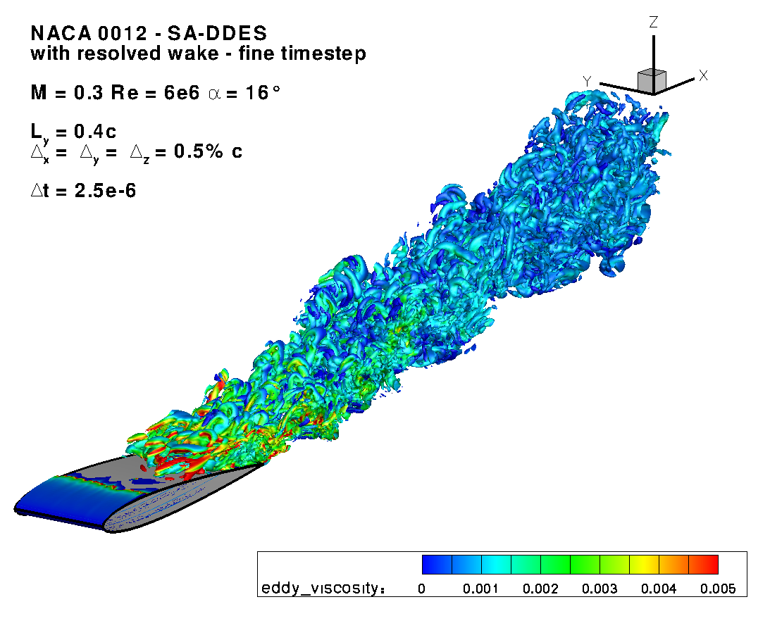
| Fluid structure coupling between the flow solver TAU and a Nastran FEM model | Propagation of the detached wake on a profile with subsonic incident flow | Numerical simulation with hybrid RANS-LES methods in the area of the shock buffet |
 |
 |
 |
| For a larger view please click on the picture! | ||
Publications
Dipl.-Ing. Sebastian Illi, Th. Lutz and E. Krämer:
Transonic Tail Buffet Simulations on the ATRA Research Aircraft
Notes on Numerical Fluid Mechanics and Multidisciplinary Design, Volume 123, Springer, Germany, 2013.
Dipl.-Ing. Sebastian Illi, P. Gansel, Th. Lutz and E. Krämer:
Hybrid RANS-LES Wake Studies of an Airfoil in Stall
CEAS Aeronautical Journal, Volume 4, Issue 2, pp 139-150, Springer, Germany, June 2013.
P. Gansel, Dipl.-Ing. Sebastian Illi, Dr. Th. Lutz and Prof. Dr.-Ing. Ewald Krämer:
Numerical Simulation of Low Speed Stall and Analysis of Turbulent Wake Spectra
The 15th International Conference on Fluid Flow Technologies, Budapest, Hungary, September 4-7, 2012.
P. Gansel, S. A. Illi, A. Kalimullina and Th. Lutz:
The Spectral Analysis of Unsteady Pressure Coefficient at the Wing Trailing Edge
16th International Conference on the Methods of Aerophysical Research, Kazan, Russia, August 20 - 26, 2012.
Dipl.-Ing. Sebastian Illi, Th. Lutz and E. Krämer:
On the capability of unsteady RANS to predict transonic buffet
Third Symposium "Simulation of Wing and Nacelle Stall", Braunschweig, Germany, June 22 - 23, 2012.
A. Klein, Dipl.-Ing. Sebastian Illi, Th. Lutz and E. Krämer:
Wall Effects and Corner Separations for Subsonic and Transonic Flow Regimes
High Performance Computing in Science and Engineering '11, Springer, Germany, 2012.
Dipl.-Ing. Sebastian Illi, Th. Lutz and E. Krämer:
Improved physical understanding and modeling – DES/LES & PIV
CFD and Experiment – Integration of Simulation, Göttingen, Germany, April 5 - 6, 2011.
Dipl.-Ing. Sebastian Illi, Dr. Th. Lutz and Prof. Dr.-Ing. Ewald Krämer:
Simulation of pressure and shock induced separation using DES implementations in the DLR-TAU Code
Second Symposium "Simulation of Wing and Nacelle Stall", Braunschweig, Germany, June 22 - 23, 2010.
Links
Official ComFliTe website of the DLR
Federal Ministry of Education and Research

Contact: Dipl.-Ing. Katharina Wawrzinek, Dr.-Ing. Thorsten Lutz
Background and motivation
Turbulences in the inflow, as they occur in the atmosphere, cause load fluctuations and can strongly influence the aerodynamics of an airfoil, especially in the stable area. A major goal of the research group is the study of these complex interactions and the improvement of numerical calculation models to predict the occurring effects. Within the framework of this new subproject, simulations on two reference configurations using a Reynolds Stress Model of turbulence and the new hybrid method of Detached-Eddy Simulation will be carried out complementary to the work of the partners. The subproject contributes to the process development with a model for the detection of anisotropies in synthetic turbulence generation. The aim of the work is the validation of these methods and the analysis of the interactions by parametric investigations. The influence of artificial two- and three-dimensional disturbances on a high-lift configuration measured in a wind tunnel as well as the interaction of an atmospheric inflow with a high-lift wing are considered. In addition to the effects of turbulent inflows on pressure distribution, loads and stall properties of wings, this subproject will also specifically investigate the influence on the development of wing wake, which is relevant for the inflow of a tail unit.
Objectives in the IAG work packages
- Analysis of the transient aerodynamics of aerofoils with inhomogeneous inflow
- Improvement of synthetic turbulence generation by a physically consistent anisotropy model
- Validation of the simulation methodology for 2D and 3D disturbances in the wind tunnel
- Gain of knowledge for flying at border areas near maximum lift in disturbed atmosphere:
- Influence of atmospheric inflow on loads and stall properties of a wing with a slit flap
- Influence on the wing wake and the inflow of a tail unit
Links
Official FOR1066 website of the TU Braunschweig
German Research Foundation
Contact: Dipl.-Ing. Philipp Gansel, Dr.-Ing. Thorsten Lutz
Background and motivation
The main objective of the DLR-led joint project HINVA (High-Lift In-Flight Validation) is the development and improvement of prediction methods for the maximum lift of commercial aircraft. For this purpose, detailed flight tests, cryogenic wind tunnel tests and extensive numerical simulations will be carried out. The Airbus A320 ATRA (Advanced Technology Research Aircraft) of DLR serves as the test vehicle. The flow conditions during the stall manoeuvre will be examined for subsonic aircraft with landing and cruise flight configuration. By using modern test and measurement technology, a large database will be obtained during the extensive flight tests, which will serve to validate and evaluate the numerical and experimental methods and contribute to their improvement. In addition to the project partners DLR, Airbus and ETW, the TU Berlin, TU Braunschweig and the University of Stuttgart are represented in the project.
Work at the IAG
At the IAG, numerical investigations are carried out on the interference behaviour of wing and tail unit flow as well as on the trim of a transport aircraft in the low-speed stall area. On the basis of the cruise flight configuration of the ATRA, the local spatial discretization of the wing wake, the fuselage boundary layer and the tailplane itself is investigated with regard to its influence on the inflow of the tailplane. The linear Ca-range is calculated with RANS- and with detached wing boundary layer with URANS-methods. The flow instationarities at the trailing edge of the wing and their propagation to the tailplane are evaluated with regard to the contained spectra and length scales of the turbulent flow, in order to finally gain a statement about their effect on transient elevator loads. In addition, the effects of a numerically determined trim angle of the tail unit compared to a trim angle determined in the flight test are analyzed. On a configuration with simplified wing geometry an exemplary Detached-Eddy-Simulation shall allow the comparison of this simulation method with temporally and spatially resolved turbulent structures to the modelled approach of the RANS equations. The influence of geometric simplifications by neglecting engine and flap track fairings is estimated with RANS methods.
Publications
- Dipl.-Ing. Sebastian A. Illi, P. P. Gansel, Dr. Th. Lutz and Prof.-Ing. E. Krämer:
Hybrid RANS-LES Wake Studies of an Airfoil in Stall
accepted by CEAS Aeronautical Journal, Springer, Germany, 2012. - P. P. Gansel, Dipl.-Ing. Sebastian A. Illi, Dr. Th. Lutz and Prof.-Ing. E. Krämer:
Numerical Simulation of Low Speed Stall and Analysis of Turbulent Wake Spectra
Proc. 15th International Conference on Fluid Flow Technologies, Budapest, Hungary, September 4-7, Vol. I, pp. 199-206, 2012. - P. P. Gansel, Dipl.-Ing. Sebastian A. Illi, A. Kalimullina and Dr. Th. Lutz
The Spectral Analysis of Unsteady Pressure Coefficient at the Wing Trailing Edge
16th International Conference on the Methods of Aerophysical Research, Kazan, Russia, August 20 - 26, 2012.


Project description
The Institute of Aerodynamics and Gas Dynamics at the University of Stuttgart is involved in the SOFIA project, a joint project between NASA, DLR, the Institute of Space Systems at the University of Stuttgart and other German and American institutions and companies. The 20-year project focuses on a flying observatory, a Boeing 747 SP with an integrated infrared mirror telescope for astronomical remote sensing.
Infrared radiation provides information about the formation of stars and solar systems, and allows a glimpse into the past. Water vapour absorbs the IR radiation, in the lower part of the earth's atmosphere only a small part of the radiation arrives. Above the tropopause (about 12-15 km altitude), good observation conditions already prevail. Compared to a satellite base, the airborne observatory offers the advantage of considerably lower costs and almost unlimited positioning possibilities. The instruments can be optimized during the flights and permanently adapted to the state of the art.
The mirror telescope (diameter 2.7 m) is located in the rear part of the fuselage, a hole cut into the fuselage structure ensures an unobstructed view to the outside. During take-off, this hole is closed by a door, which is opened for observation during flight.
Background and motivatin
The overflow of the cavity leads to strong turbulences and self-excited pressure fluctuations in the area of the mirror, whereby under flight conditions without active or passive damping mechanisms sound levels of up to 160 dB are achieved in the cavity, which in turn lead to body vibrations. In order to optimize the positioning accuracy of the telescope in order to achieve the highest possible observation quality, pressure fluctuations must be suppressed. Several active and passive methods are available to influence the boundary layer upstream of the cavity or the free shear layer.
Objectives in the IAG work packages
- Investigation of SOFIA cavity aeroacoustics with CFD (Computational Fluid Dynamics) and CAA (Computational Aero Acoustics)
- Studies on passive and active flow influencing
- Analysis of the influence of flow phenomena on the positioning accuracy of the telescope
- Testing of hybrid RANS-/LES methods for the simulation of caviy flows
- Evaluation of aero-optical properties of free shear layers using CFD
- Detailed analysis of the SOFIA cavity flow using pressure sensors, thermocouples and optical cameras during flight tests.
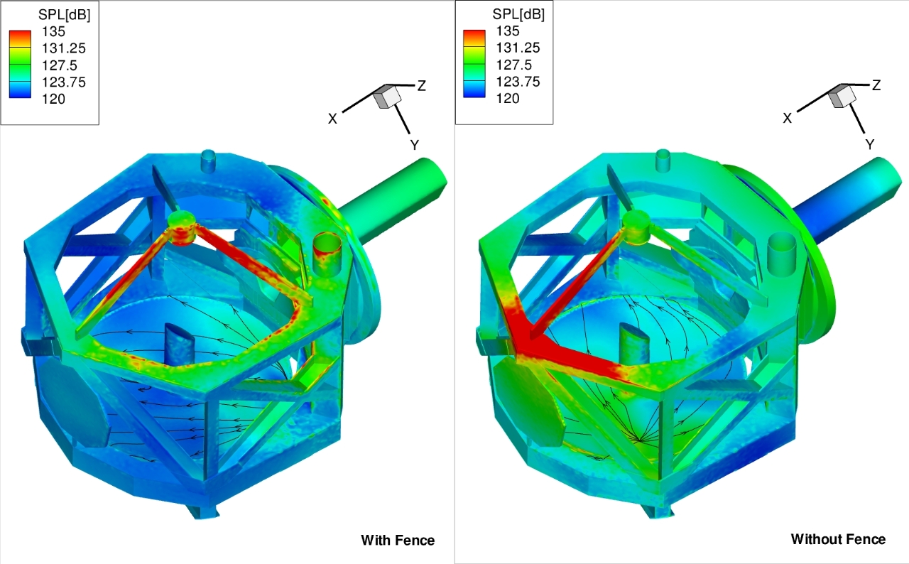
Results
| Influencing the shear layer over the cavity with a 3D fence |
 |
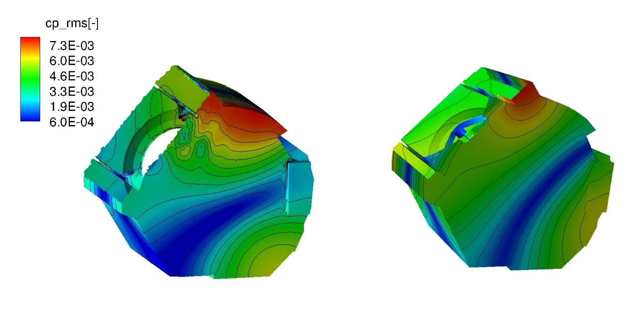
| Impact of passive flow influence on the telescope |
 |
| Comparison of CFD and CAA in the prediction of cavity acoustic modes |
 |
Publications
S. Schmid, Th. Lutz and E. Krämer:
Simulation of the Unsteady Cavity Flow of the Stratospheric Observatory For Infrard Astronomy
IUTAM Symposium on "Unsteady Flows and their Control", Vol.14, Springer Berlin Heidelberg New York 2009
S. Schmid, Th. Lutz and E. Krämer:
Passive Control of the Flow Around the Stratospheric Observatory For Infrard Astronomy
AIAA Paper 2008-6717, 2008
Links
Contact: Dipl.-Ing. Dina-Marie Zimmermann, Dr.-Ing. Thorsten Lutz
Background and motivation
In boundary areas of the flight envelope, strongly transient inflows at the tail can be caused by detached and thus temporally fluctuating boundary layer conditions at the wing. The transient aerodynamic forces excite dynamic modes of the structure, which must be taken into account in the load calculation of the tailplane. In addition, detachments at the wing affect the downwind and thus change the inflow conditions of the tail, which can negatively influence its effectiveness. In the LuFo IV project ATLAS investigations are therefore carried out on the transient inflow of the tail in the wake of a detached wing flow. Based on a characterisation of the transient inflow at the tail from numerical simulations of detached wing flows, a model is developed to describe the fluctuations in the tail area.
Objectives:
-
Establishment of an efficient chain providing suitable input data for the method used by project partners to calculate transient tailplane loads.
-
Findings on the influence of inflow parameters on the transient fluctuations in the tailplane inflow.
-
Methodology for the efficient determination of transient inflow data at the tail unit based on the flow state at the wing from RANS simulations.
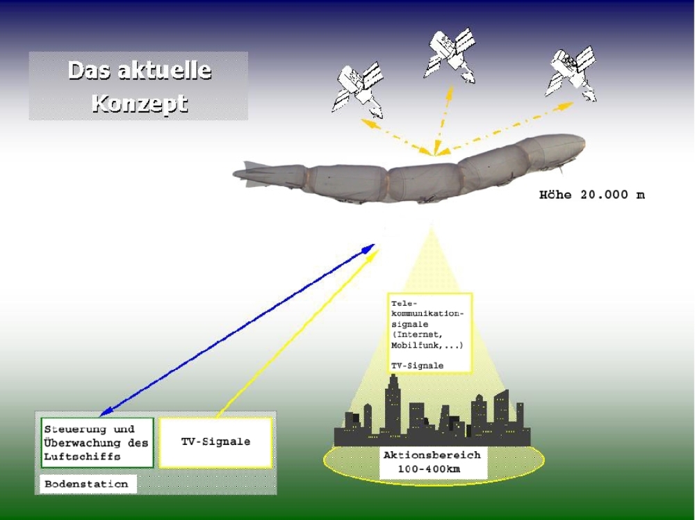
In times of constantly increasing mobile data traffic with ever faster data transmission rates and required bandwidths, it is becoming increasingly necessary to look for alternatives to the existing ground-based and satellite-based solutions that are able to cope with the data volume of the future and guarantee area-covering and cost-effective use. At the Institute for Statics and Dynamics of Aerospace Structures (ISD) the test vehicle of a multi-segment airship platform ("airworm") has been tested for several years. Equipped with telecommunication devices, the platform is to be positioned at a height of 20 km in the stratosphere as stationary as possible above a fixed point on Earth due to the favourable wind conditions prevailing there (Figure 1). With a corresponding position outside the commercially used airspace of up to about 15 km, the lowest wind speeds in the upper stratosphere occur in this altitude range. On average, these are around 50 km/h in summer and 100 km/h in winter, although considerably higher values may occur in the short term. As is the case with most aircraft, the minimization of structural mass is of decisive importance in the design of high-altitude platforms. In a non-rigid airship, this consists of the mass of the hull and the tail units as well as the payload. The hull mass results from the maximum internal overpressure that the hull must withstand. This maximum internal overpressure is made up of the operating overpressure and the maximum differential pressure of the carrier gas at high pitch.
 |
|
Figure 2: |
The operating pressure ensures that the airship can withstand under all flight conditions the static bending stresses resulting from an uneven distribution of lift, payload and design mass (in particular the tailplane) as well as the dynamic bending stresses caused by the tailplane and ammunition moments during stabilisation and control of the airship. Both bending stresses and thus the hull mass increase with increasing length-diameter ratio of the airship, whereby the proportional mass of the tail units decreases. In the case of a sphere, both bending stresses disappear, so that five quasi-spherical segments were arranged one behind the other in order to achieve the lowest possible hull mass and at the same time a high aerodynamic quality. The loose coupling of the segments results in an additional form instability. However, the multi-segment "airworm" can be stabilized, as demonstrated in numerous flights of the prototype (Figure 2), by appropriate control using differential thrust of the propellers attached laterally to the first three segments.
 |
| Figure 3: Prototype |
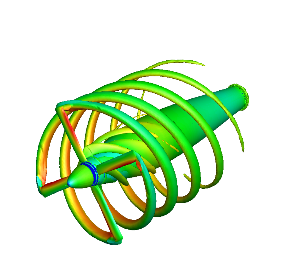
The IRON BIRD system test bench is being developed for the simulation of all systems of this airship-supported elevation platform within the framework of the AirChain project financed by the Landesstiftung Baden-Württemberg foundation. In addition to the dimensioning of the components on board and the complex control system, the IRON BIRD is also used for extensive testing of the overall system. Within the scope of this project, work at the IAG is concerned with aerodynamic problems. This includes the calculation of the propeller maps for the existing controllable pitch propellers.
These are attached laterally to the first three segments of the "airworm" and provide the necessary propulsion, whereby the stabilisation and directional control of the multi-segment airship is also achieved by differential thrust. These serve as the basis for the flight-mechanical models of the flight control systems.
 |
| Figure 4: Wind Tunnel Model |
Although today's theoretical approaches and their implementation in numerical simulations are subject to continuous improvement, the validation of the obtained results by means of wind tunnel tests is still an important component in the design process of a flying object. This applies in particular to the very strong three-dimensional airship flow, which is characterized by massive separation. This still poses great challenges for today's computational methods, especially in the case of the transient detachments that frequently occur at large angles of attack or thrust due to the low possible flight speeds under the influence of gusts and flight manoeuvres. For novel configurations such as the "airworm", in which the individual segments can additionally assume different flight angles to each other, very complex flow-mechanical phenomena arise, especially at the bends (Figure 3). For such multiple buckled configurations no aerodynamic data base exists yet, so that experimental investigations are necessary to determine the coefficients and to validate flow solvers. Figure 4 shows the configurations to be investigated within the wind tunnel measurement series.
 |
| Figure 5: Model in the wind tunnel |
For this purpose, a 4m long wind tunnel model was created for the Gust Wind Tunnel of the institute, at which the required segment angles can be adjusted (Figure 5). In addition to the total loads on the configuration, the individual segment loads must also be determined. The former are recorded with the aid of a rope-supported model suspension. The model, sufficiently ballasted, is suspended from six ropes equipped with a force transducer. The aerodynamic loads on the model are determined by means of the rope forces and the rope directions, for which the individual suspension ropes are each provided with three reflecting markers, the positions of which are recorded with the aid of a photogrammetric method (Figure 6). The individual segment loads can be determined by integrating the pressure distribution on the model surface.
Multi Ojective Dynamical Aircraft Synthesis
High-precision modeling of flight dynamics and aerodynamics for a flexible aircraft program aeronautical research 2003-2007 of the BMWT. The aim of the project is to establish a method for the generation of high-precision state space models of a flexible aircraft. For the first time, nonlinear transonic and viscous effects should be considered Figure 1: Process chain MODYAS Figure 2: Deformation of a dynamically stressed wing At IAG, the necessary RANS calculations for the trimmed, aeroelastically deformed aircraft are performed. For this purpose, the RANS solver FLOWer is coupled with a method for the automatic generation of structured multi-block grids and the FEM program Nastran modular. In the weakly coupled CFD-CSD simulation, not only the aeroelastic wing deformation but also the deformations of the fuselage and the tail units are to be taken into account. The results of the aeroelastic simulation serve the DLR Institute of Aeroelasticity as a basis for the calculation of the transient air force matrices using a Transonic Doubled Lattice (TDLM) method. The Institute of Flight Mechanics and Flight Control (IFR) uses these air force matrices as the basis for creating a state space model of the flexible aircraft.
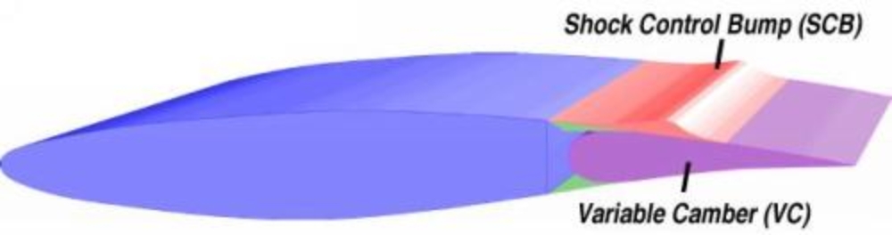
The project deals with concepts and aerodynamics of adaptive transonic wings. To cope with the problem of flight at transonic Mach numbers adaptive mechanisms are introduced. Aerodynamic efficiency at off-design conditions is improved by the application of a shock control bump (SCB), a concept first introduced in 1992 by Ashill, Fulker and Shires, on a variable camber (VC) airfoil. Since a SCB has to be properly shaped and positioned to generate a favourable effect, relevant geometrical parameters are investigated using direct numerical optimisation. An optimisation environment was developed consisting of a hybrid optimiser, a geometry module and a coupled Euler boundary-layer code. For a specified off-design condition bump shapes are optimised, while the influence of various geometric bump representations is investigated. Shape optimisations for an adaptive bump are carried out for different Mach numbers at a fixed lift coefficient. To overcome the problem of narrow Mach regions of significant drag reduction for one-point designed bumps, multi-point designs are performed.
The physical effect of the SCB is based on the highly nonlinear character of transonic flows. The SCB maps the contour of supercritical wing sections onto a smaller scale thus inducing isentropic compression waves upstream of the shockwave. This leads to a significant decrease of wave drag.
Determination of the exact flight condition in real flight represents a sophisticated task. Thus it is anticipated that SCBs for practical use must yield a reduced sensitivity to small changes of the onset flow. Because of the narrow Mach region of reduced drag coefficients for a one-point designed SCB multi-point designs were introduced. The objective function for the multi-point optimisation was changed to be represented by the sum of two drag coefficients at two different Mach numbers. On the left hand side the drag coefficient is plotted vs. the Mach number for a one-point design and several two-point optimised bumps. Since no weighting factors were involved in the optimisation process, the lower edge of the Mach-region implicitly has a lower priority than the upper edge since it introduces less wave drag that can be reduced. Thus the bump optimised for the most extended region of Mach numbers even shows a higher drag coefficient for the lower design Mach number compared to the clean airfoil while being favourable in the remaining design region. However, it can be stated that at the cost of less maximum drag reduction the region in which the bump is effective is broadened.
| Figure 2 and 3: Polar Diagrams of Adaptive Wing |
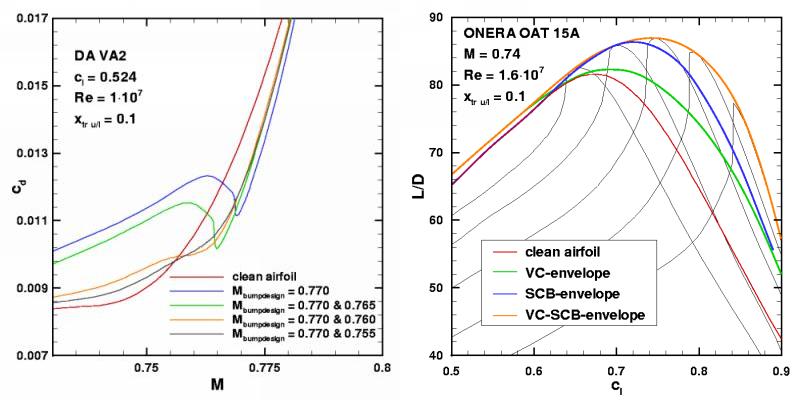 |
Because of its wave drag reducing capability an SCB applied additionally onto a VC airfoil promises a further increase of the aerodynamic efficiency. Direct numerical optimisations for a VC-SCB combination were carried out in order to estimate the additional improvement. On the right hand side the lift to drag ratio is plotted against the lift coefficient for the clean airfoil, the envelope of a VC-airfoil (green line), the envelope of a SCB-airfoil (blue line) as well as the envelope of a VC-SCB combination (orange line). Significant additional gains for the combination are visible. Investigations of the resulting optimised bump geometries of the VC-SCB combination show a noticeably reduced bump height compared to the optimised SCB only geometry. Further investigations regarding this project can be found in the following publications:
A. Sommerer, Th. Lutz and S. Wagner:
Numerical Optimization of Adaptive Transonic Airfoils With Variable Camber
Proceedings 22nd ICAS Congress, Harrogate, United Kingdom, August 27 - September 1, 2000, ICAS Paper ICA2.111
A. Sommerer, Th. Lutz and S. Wagner:
Design of Adaptive Transonic Airfoils By Means of Numerical Optimization
Proceedings ECCOMAS 2000: European Congress on Computational Methods in Applied Sciences and Engineering, September 11-14, 2000, Barcelona, Spain

Research Group Airship Technology (FOGL)Aircraft.
The Airship Technology Research Group (FOGL) was established by the German Research Foundation (DFG) at the beginning of 1997 at the University of Stuttgart and was funded for a total of six years. The initiator of the research group was Prof. Dr.-Ing. B. Kröplin from the Institute for Statics and Dynamics of Aerospace Structures (ISD). In addition to the ISD, the Institute of Aerodynamics and Gas Dynamics (IAG), the Institute of Flight Mechanics and Flight Control (IFR) and the Centre for Solar Energy and Hydrogen Research (ZSW) were involved. The objective of the research group was to deepen the understanding of relevant physical relationships and phenomena as a basis for the development of new tools and for the adaptation of existing tools for the design and analysis of modern airships.
Since the peak phase of the airships, hardly any scientific investigations have been carried out on the aerodynamics of "lighter-than-air" configurations. At the beginning of FOGL's work, no current published aerodynamic data was available that would serve as a sound basis for validating modern measurement techniques. This concerned on the one hand studies on the topology of the fluid bed separation from the fuselage and on the development of the associated wake, as well as investigations on interference effects between fuselage and tail fins. The results have deepened the understanding of the relevant fluid mechanics phenomena. In addition, they served as a basis for physically meaningful modelling within the framework of a parallel process development. One focus of the theoretical work was the development and implementation of an efficient coupled 3D panel boundary layer method, in which airship-specific aerodynamic phenomena are specifically captured. Approaches for the higher-quality modelling of free vortex layers, as they can detach from the inclined hull or the side or front edges of the tail units, have been developed. The resulting calculation program UNIPAC enables the stationary analysis of driven LTA configurations as well as the recording of relevant transient effects with a justifiable computing time requirement.
A further focus of the theoretical work was the performance of RANS analyses (Reynolds-Averaged-Navier-Stokes) for the reference configuration LOTTE, which was measured in detail. Extensive comparative calculations document characteristic differences between different turbulence models and knowledge and experience could be gained for the meaningful selection and application of suitable models (as well as for the design of structured grids).
 und gemessene Druckverteilung für das Luftschiff LOTTE") |
| Comparison calculated (RANS) and measured pressure distribution for the airship LOTTE |
 |
| Measurements on LOTTE in the Gust Wind Tunnel of the IAG |
 |
| Boundary layer measurements and flow visualization on the Zeppelin NT in flight test |
The results achieved within the framework of FOGL's work have been documented in numerous publications and can also be found, for example, in the specialist book "Lighter than Air - Transport and Carrier Systems".
The aim of the ELFLEAN project in the Aviation Research Programme (LuFo) V-3 is the investigation of aircraft configurations with surface propellers.
Dr.-Ing. Thorsten Lutz

Thorsten Lutz
Dr.-Ing.Head of working group Aircraft Aerodynamics / Head of working group Wind Energy